LoRa - Long Range - spread spectrum modulation
 LoRa is a transmission technology which sends small data packets such as text messages, geo positions, measured values, control commands, etc. over long ranges with low power and low energy consumption. Due to the low power consumption and an additional use of a deep sleep mode, a long autonomy can be achieved even with accumulator/battery power supply. In amateur radio, however, this advantage is not at the top of the advantage list since we will mostly feed nodes from an ACCU only in portable mode. On fixed sites (QTH) are mostly mains or solar supply with modern LiFePO4 batteries with large capacity available.
The range of LoRa radio modules can, depending on the frequency and antennas used, bridge distances > 20km in rural areas and >5km in the city. Another advantage is the low cost of the hardware which results from the large number of LoRa modules and the use of standard components.
So why not use these micro-modules for applications in the Citizen Science environment to create applications like:
- Measured values such as temperature, air pressure, humidity, ground radiation, ...
- Text messages off-grid
- GPS geodata in APRS format (a compressed protocol for transmission).
- Messages for the EMERGENCY/CAT case
to be transferred.
LoRa & Amateur Radio?
MeshCom has already been rolled out on amateur radio frequencies for quite some time and has contributed very well to the understanding of this transmission technology. LoRa modules with a 70cm (433 MHz) LoRa chip are used. The key point in a common network is however the use of a common protocol which is to be defined in this project. Today, not only in Austria, an OE-LoRa format is used for the transmission of GPS packets. This independent HAM-IOT project runs on coordinated frequencies of 433.775 MHz for the uplink to the LoRa access point and 433.900 MHz for the downlink.
Narrowband versus spread?

Die Übertragung mittels einfacheren Modulationen (2-FSK, 4-FSK) konnte auf schmaler Bandbreite (< 3 kHz) erfolgen. Mit CRC und FEC konnten Fehler am Übertragungsweg zum teil bereits recht gut in den Griff bekommen werden.
However, if transmission paths are to be kept robust against interference, development is increasingly moving towards a more broadband modulation. This can be achieved by using several carriers with partly redundant information.
LoRa uses a special frequency spread modulation (English spread spectrum). In principle, this modulation can be used on all frequencies, in the MeshCom project we use the 433 MHz frequency range in Europe.
LoRa parameters:
Spreading Factor (SF Spreading Factor)
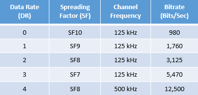
The spreading factor determines how many symbols are used to encode user data. This is specified for LoRa modulation from SF6 to SF12. For example, 128 symbols are used for SF7, and for SF11 there are even 2048 symbols for encoding the identical user data. SF7 is the standard spreading factor, which has a runtime of about 120 milliseconds for the data transmission of 64 bytes. With SF11, the runtime is even well over one second.
Bandwidth (BW Bandwidth)
The bandwidth for LoRa modulation can be set; defined bandwidths include 31.25 kHz, 41.7 kHz, 62.5 kHz, 125 kHz, 250 kHz and 500 kHz. A smaller bandwidth requires significantly more time for a message transmission. Bandwidths below 125 kHz only work with special LoRa hardware that uses, among other things, a TCXO (Temperature Compensated Crystal Oscillator) and has special hardware support for it. Stable with all LoRa chipsets it works from 125 kHz. Exclusively the 125 kHz bandwidth is defined for the LoRaWAN protocol. The RadioShuttle protocol supports all bandwidths, but 125 kHz is also recommended.
The bandwidth is also important for channel selection: if, for example, a bandwidth of 125 kHz is used, the next free channel must be further away than the bandwidth. The center frequency for MeshCom 4.0 has been set at 433.175 MHz.
Coding rate (CR Coding Rate)
The encoding rate refers to the proportion of the transmitted bits that actually carry information. The encoding rate can be 6/8, 4/8, and so on. So if CR is 4/8, we transmit twice as many bits as those that contain information. If there is too much interference in the channel, it is recommended to increase the CR value. However, the increase of CR value also increases the duration of transmission.
Symbol (TS Symbols)
LoRa a chirp spread spectrum modulation. The transmitted data, which is a symbol, is represented by a chirp signal with a frequency range from -to. In LoRa modulation, we can configure the symbol by changing the Spreading Factor and Bandwidth parameters. According to the Semtech AN1200.22 application note, a symbol takes one second to transmit, which is a function of the bandwidth and spreading factor and can be represented by the following equation:

Fig. Overview of relationship between SF, BW and bit rate
LoRa bit rate calculation: https://unsigned.io/understanding-lora-parameters/
LoRa RF parameters
RSSI and SNR
In wireless communication, a receiver needs a good signal strength and signal-to-noise ratio to separate the original signal from the modulated carrier. This section contains information on two of the most commonly used signal strength indicators - RSSI and SNR.
RSSI
RSSI (Received Signal Strength Indicator) is a relative measurement that allows you to determine if the received signal is strong enough to establish a good wireless connection from the transmitter. Since LoRaWAN supports bidirectional communication, RSSI is an important measurement for both gateways and end devices. RSSI is measured in dBm and its value is a negative form. The closer the RSSI value is to zero, the stronger the received signal.
In addition to the output power of the transmitter, the following factors in particular influence the RSSI:
- Path loss
- Antenna gain
- Cable/plug loss
SNR
SNR (Signal-to-Noise Ratio), often written as S/N, is the ratio of the received signal power to the noise floor. SNR is commonly used to determine the quality of the received signal.
The SNR can be calculated using the following formula and is often expressed in decibels (dB):
SNR (dB) = Preceived_signal (dBm) - Pnoise (dBm)
If the RSSI is above the noise floor, the receiver can easily demodulate the signal.